|
From CertCities.com
|
|||||||||||||||||||||
|
Feature UPDATED: Fiber Optics 101: A Primer As a networking professional, sooner or later you'll need to understand the inner workings of fiber optic networking: What's the difference between singlemode and multimode, and how do they affect transmission speed? How can you get the longest distances? How can CWDM save you money? This article explains all of the above and more. by Randy Bird 9/19/2001 -- (Updated 11/04): Fiber optic cabling has been used for long distance voice communications for more than 30 years, but voice was and is a slow-growth area. Over the last 10 years, however, the explosive increase in the Internet and other data communications applications has resulted in enormous requirements for bandwidth. As fiber is the technology best suited to providing this bandwidth, its use continues to spread out from the core backbones to enterprise networks and right on down to the desktop. While from a distance fiber optic communications may appear to be different from more familiar technologies, in reality the basics are pretty simple and easy to comprehend. This article is intended to shed some light on the principles and practices involved in fiber optics, so that you will have a working knowledge of what the elements of the systems are and how they work. Why Fiber?
The only real advantage copper has had over fiber has been cost. As the number of fiber installations increases, and the technology to terminate the ends improves, the gap in cost between pulling fiber and copper cabling is getting fairly small. However, there is still a fairly wide difference in the cost of the electronics interfacing to the cabling, though again with volume this is coming down. Fiber Construction
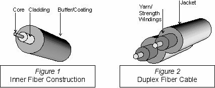
The core, where all the action takes place, is covered with a thin cladding designed to reflect and contain the light within the core itself. This in turn is surrounded by a buffer or coating for mechanical strength. Unjacketed fiber strands like this are used within equipment and patch panels, but they are too fragile to be out in the open and certainly couldn't be pulled. Two or more fiber strands are wrapped in yarn or some other type of material to provide tensile strength, then covered with a jacket to protect and hold the whole mess together. As with copper wiring, different materials with varying flammability and smoke ratings are required for plenum and non-plenum cabling. Fiber cabling is frequently routed within a conduit of some sort, either metal or plastic, providing an additional degree of protection. Singlemode v. Multimode Fiber
Figure 3: Multimode Fiber, Multiple Light Paths With multimode fiber, light that is injected into the core can travel in many paths through the cable; think of it as rattling around inside a tube. Because these paths are each slightly different in length, the time to traverse a length of fiber can vary a little bit. This variance in time has the effect of spreading pulses of data out, which limits the bandwidth of multimode fiber – and the longer the run, the lower the bandwidth. Newer fibers can be made with a variable index of refraction in the glass of the core to reduce this effect, but in all cases multimode fiber is modal-bandwidth limited. Because of this, multimode fiber has been primarily used in LANs where the distance limitation has not been a problem.
Figure 4: Singlemode Fiber, One Light Path Singlemode fiber, on the other hand, has such a narrow core that the light takes only one path through the glass. Hence, singlemode fiber is not limited by modal bandwidth and so supports vastly greater data rates than multimode fiber. Pulse spreading in singlemode fiber does still exist, due to the fact that different light wavelengths actually travel at slightly different speeds in the glass core, but this "chromatic dispersion" is inconsequential until you get into gigabit speeds. Even there, fibers have been developed that reduce or eliminate the problem, so that the singlemode fiber installed today can support data rates in the tens of gigabits per second over distances on the order of 100 km. All of the fiber installed in WANs and frequently in LANs spanning campuses of any size, is singlemode. The fiber itself is not much more expensive than multimode, though the small core size makes it more touchy to terminate correctly. There is, however, still a significant difference in the cost of the optoelectronics used with singlemode fiber compared to those used with multimode. Fiber Optic Connectors
Figure 5: Standard Fiber Connectors Recently, several new "small form factor" fiber optic connectors have entered the fray. Each of these takes up the same space as a twisted pair RJ-45, and is about half the size of the traditional connectors. The most common of these are the Volition VF-45, the MT-RJ and the LC, with the latter two fighting for the most market share over the last few years. In particular, the LC appears to be pulling ahead in the race, with the rapid increase in shipments of replaceable optoelectronic transceivers called “SFPs” (small form factor pluggable) with LC connections.
Figure 6: Small Form Factors (SFF) Connectors Regardless of the connector used and the manufacturer's claims, connectors are always a trouble spot in fiber optic networks. Because of the small size of the mating fibers, the slightest contamination can result in blocking a fair amount of light and causing a bad, or even worse, intermittent connection. Fiber optic connectors should always be kept with the manufacturer's protective dust cap in place until the moment of mating, and excessive connection/reconnection discouraged. If dirty fiber is suspected, it should be cleaned with industrial-grade alcohol (drugstore-grade alcohol can leave a film when it evaporates) and a lint-free tissue. A good, clean fiber connection might have less than 0.5 dB of loss; a poor one, 2 dB or more. These losses are roughly equivalent to those seen in one to several miles of unspliced fiber optic cable, so you can see how important the connector quality is to the overall system. See the Light
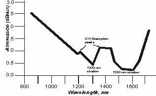
Figure 7: Fiber Loss Versus Wavelength As inexpensive light emitting diode (LEDs) and Vertical Cavity Surface Emitting Laser (VCSEL) transmitters operate well at 850 nm, that wavelength is also used. These wavelengths are all out in the infrared range of the spectrum; you can see 850 nm as a dark red light, but 1310 nm and 1550 nm are invisible to the naked eye (the output power of these transmitters is limited to about 1 milliwatt in order to be categorized as Class I Eye Safe devices, but it is never a good idea to look into a transmitter.) Transmitter Types Limiting Factors
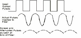
Figure 8: Light Pulse Degradation Roughly speaking, 850 nm and 1310 nm multimode systems can operate at distances from a few hundred meters to a couple of kilometers; see Table 1 below for examples. 1310 nm FP laser singlemode systems can range from 10 to 40 km; DFB lasers can reach up to 100 km with good fiber. If the distance spanned exceeds these limits, the light must be amplified directly (with a device known as an Erbium Doped Fiber Amplifier) or converted to electricity, regenerated, amplified, and converted back to light.
* 62.5µm / 50µm fiber
The Future of Fiber For more information on this topic, see Randy Bird's "Fiber Optics 102: Implementation Considerations" article, updated 11/04. Questions or comments? Post them below! Randy Bird is a consultant with 20 years of experience in networking hardware and software. He can be reached at . |
|||||||||||||||||||||
|
top Copyright 2000-2005, 101communications LLC. See our Privacy Policy. For more information, e-mail . |
|||||||||||||||||||||


