Fiber Optics 102: Implementation Considerations
You asked for it, you got it: Randy Bird follows up his popular Fiber Optics 101 article with these tips for implementing and troubleshooting fiber LANs.
by Randy Bird
9/19/2001 -- A few months ago, in my article "Fiber Optics 101," we discussed some of the theory and background of fiber optic communications systems. This article continues from there, taking that information and showing how it can be applied to solving real-world networking problems.
For the purposes of this article, we will focus on local area network applications, either within a building or through a campus. LANs are typically installed and maintained by the user, as opposed to wide area networks (WANs) which usually belong to and are maintained by a carrier (although "dark fiber" capacity may be leased directly by the user). In addition, because we are talking about LANs, that also implies that we are talking about Ethernet, 10/100/1000 mbps, and not other standards such as OC-x or SONET.
Why Fiber LANs?
To review, the primary advantage of fiber over copper is the ability to operate over a greater distance at higher speeds. The Ethernet standards for unshielded twisted pair cabling limit point-to-point distances between nodes to 100 meters when using the appropriate grade of wiring. Electrically noisy environments, substandard cabling or poor workmanship in connections may further limit this distance.
Fiber optic Ethernet standards vary in the distances provided as a function of data rate and fiber type, but are always more than 100m. Some of the applications for this additional distance are selectively connecting nodes further than 100m from a wiring closet; tying copper switches located in distant wiring closets to a communications center; linking buildings across a campus; or providing home-run wiring from all desktops to a central location without intermediate wiring closets. Whatever the application, once the network architecture defines one or more fiber optic runs, the same principles apply, and we’ll try to help you understand what is needed for a reliable, cost-effective installation.

Fiber Optic Media
Copper cabling is characterized as Category 3, 5, 5e, etc., where the category rating combines a number of specifications for different parameters such as impedance, bandwidth and crosstalk. Fiber is a bit more complex, as ongoing development of both the manufacturing process of the fiber itself and the equipment that uses it have resulted in many improvements over the baseline ANSI or ISO specifications. But in general, remember from the last article that there are two fundamental types of fiber: singlemode and multimode. Multimode has more performance limitations than singlemode, but is less expensive on a system level. LANs have usually been wired with multimode fiber (WANs are always singlemode), but increasing data rates are causing an upswing in singlemode -- even within a building.
If you are dealing with an installation where the fiber is already in place, you need to play the hand you have been dealt. With luck, there are installation records that can be used to determine the specifications of the fiber. If not, you will need to measure certain parameters and rely on the minimum standards for others where measurement is not practical. We will discuss the critical elements below.
Singlemode v. Multimode Fiber
If you are working on a new installation, you have the freedom to choose the type of fiber to be deployed and, of course, to live with the consequences. The application, expected lifetime and economics of the installation guide this choice. The fiber to the desktop application is straightforward: Unless you have an unlimited budget or a very peculiar installation, put in standard duplex 62.5 µm multimode fiber. This will support gigabit data rates at distances up to several hundred meters. For inter-building connections over a small campus, multimode fiber may also be appropriate, but if you plan to move to 10 gigabit Ethernet over the lifetime of the installation, then standard singlemode fiber would be a better choice. Intra-building equipment room interconnections have, as mentioned, traditionally used multimode fiber, but a new installation using singlemode would be future-proof if the extra cost is acceptable. In any event, for any non-desktop application, I would recommend pulling more fibers than you think you need now -- the incremental cost of multifiber cable is not that great, the labor cost involved in pulling the cable is the same, and you can always leave the additional strands unterminated until needed to save money.
Connector Installation
In addition to the fundamental choice of fiber type, you will also need to select a connector type. As we discussed last time, there are a number of competing connectors available on the market, each of which claims advantages over all others.
There are two places that connectors need to be considered: for termination of the installed fiber, and on patch cords connecting equipment to the patch panels or wall outlets where these terminations are mounted. Unless you have the training and equipment needed to terminate fiber, this chore is best performed by the professional installers who also pull the fiber. By relying on a single source to provide the installation from wallplate to patch panel, you can be assured of guaranteed end-to-end performance of the connection. Every point-to-point fiber connection should be detailed as to the cable manufacturer, manufacturer’s model number and performance specifications, as well as measured and characterized for losses on that specific link.
Patch Cords
For flexibility, pulled fibers are rarely terminated directly at active equipment. The permanent fiber in the wall eventually ends up at a connector at a wall plate or patch panel, into which a patch cord is plugged. Note that connectors terminated to the fiber itself and on the patch cord are male, as the fiber core (supported by a ferrule) is the working end; bulkhead connectors at the wall plate or patch panel can be thought of as back-to-back female connectors, allowing mating of the male fibers.
For patch cords, the general rule is that to a great extent you get what you pay for. Like ordering wine-by-the-glass in a restaurant, it’s usually best to avoid the cheapest along with most expensive alternatives and buy the best that fits within your budget.
Patch cords connecting user equipment to wall jacks should be jacketed and adequately tough to hold up to the usual sort of abuse that such connections receive. Patch cords within crossconnnect panels in data centers are frequently unjacketed as they then are much more compact, and don’t need to stand up to the punishment of exposed cabling.
Always keep the dust caps on any fiber connector until the time comes to actually plug it in -- the slightest contamination can result in significantly degraded system performance, particularly with singlemode fiber.
Bandwidth Limitations
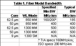
 The two main specifications of an installed fiber link are the modal bandwidth and attenuation of the connection. The modal bandwidth of the fiber is an inherent characteristic specified and guaranteed by the fiber’s manufacturer. The bandwidth of singlemode fiber for the sorts of LAN installations we are discussing is effectively infinite, and this characteristic can be ignored. For multimode fiber, it is a function of the wavelength to be used by the equipment at either end. A typical 62.5 µm fiber would have a modal bandwidth of 185 MHz-km at 850 nm and 500 MHz-km at 1300 nm. Since the 2 km specification for 100Base-FX is within the 4 km modal bandwidth limit of the fiber (500 MHz-km ÷ 125 MHz data rate), the modal bandwidth can be ignored until you get to gigabit Ethernet. There, with a bit rate of 1250 mbps, the 850 nm 1000Base-SX standard calls for a distance of 220m on 62.5 µm fiber (the higher modal bandwidth of 50 µm fiber at 850 nm allows it to support up to 550m). The two main specifications of an installed fiber link are the modal bandwidth and attenuation of the connection. The modal bandwidth of the fiber is an inherent characteristic specified and guaranteed by the fiber’s manufacturer. The bandwidth of singlemode fiber for the sorts of LAN installations we are discussing is effectively infinite, and this characteristic can be ignored. For multimode fiber, it is a function of the wavelength to be used by the equipment at either end. A typical 62.5 µm fiber would have a modal bandwidth of 185 MHz-km at 850 nm and 500 MHz-km at 1300 nm. Since the 2 km specification for 100Base-FX is within the 4 km modal bandwidth limit of the fiber (500 MHz-km ÷ 125 MHz data rate), the modal bandwidth can be ignored until you get to gigabit Ethernet. There, with a bit rate of 1250 mbps, the 850 nm 1000Base-SX standard calls for a distance of 220m on 62.5 µm fiber (the higher modal bandwidth of 50 µm fiber at 850 nm allows it to support up to 550m).
Attenuation
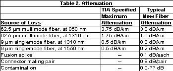
Attenuation, or losses, in a fiber link come from a variety of sources. Dispersion of the light in the fiber itself comes from absorption or scattering of light from microscopic impurities. It is a function of the wavelength of the light, ranging from 3.75 dB/km at 850 nm for minimally compliant multimode fiber down to less than 0.2 dB/km at 1550 nm for new singlemode fiber. Significant losses also occur at connector matings; while a quality new connector pair may have losses as low as 0.5 dB, any contamination at the connection point can result in significant attenuation. (In fact, the most common tech support problems in fiber installations come from dirty connections.)
 When a longer run of fiber is laid from a spool, a permanent splice is made by fusing the two ends together; the loss from these splices should be negligible if correct tools and good workmanship are present. In any fiber installation, the overall attenuation of each link should be measured and documented at the appropriate wavelengths (850 nm and 1300 nm for multimode, 1300 and 1550 nm for singlemode). The power budget of the equipment connected at either end of the link must be adequate to overcome these losses; this in particular gets to be an issue at longer singlemode runs. When a longer run of fiber is laid from a spool, a permanent splice is made by fusing the two ends together; the loss from these splices should be negligible if correct tools and good workmanship are present. In any fiber installation, the overall attenuation of each link should be measured and documented at the appropriate wavelengths (850 nm and 1300 nm for multimode, 1300 and 1550 nm for singlemode). The power budget of the equipment connected at either end of the link must be adequate to overcome these losses; this in particular gets to be an issue at longer singlemode runs.
Attenuation and Power Units of Measure
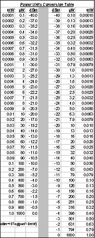
For ease of calculation, attenuation in fiber systems is specified in decibels (dB) and power in decibels relative to 1 milliwatt (dBm). Attenuation in dB is the logarithmic ratio of output power to input power: 10_log (Pout/Pin). For example, if a transmitter injects 1 milliwatt (mW) of light into one end of the link, and .001 mW reaches the other end, the attenuation is -30 dB (=10_log (.001/1)=10_-3.0=-30). Power itself is specified relative to 1 mW (i.e., 1 mW= 0 dBm, 0.1 mW = -10 dBm, .01 mW = -20 dBm, etc.) so that power budgets and losses may be calculated by subtraction and addition of reasonably-sized numbers rather than multiplication and division of very large or very small numbers. For example, if you have a transmitter that outputs 0 dBm and a fiber link that has 30 dB of attenuation, the receiver must be able to deal with a light level of -30 dBm at the far end.
A table showing conversion between various units of measure can be found at the end of this article.
Light 'Er Up!
O.K., so you now have installed or inherited a set of fiber links, hopefully all of which have been identified, labeled, measured and documented. This is now what generally is referred to as "dark fiber." In order to make use of it, active equipment needs to be provisioned at either end of a link. There are all kinds of gear that can make use of the fiber, but since here we are discussing LANs, we’ll focus on Ethernet equipment. The three principal fiber devices in this area are user equipment connections (Network Interface Cards), switches/hubs/routers and media converters.
Network Interface Cards
NICs with fiber ports are readily available from a variety of sources. While the 10 and 100 mbps Ethernet mass-market suppliers generally stayed away from fiber as the twisted pair standard was in place, in Gigabit Ethernet, the TX standard lagged and hence the Intels and 3Coms produced fiber gigabit NICs. However, in general, the volume for fiber NICs is vastly less than that of the copper versions, so specialty fiber device suppliers dominate this market.
100Base-FX network interface cards typically run between $75 to 150, compared to the current sub-$20 cost of a good 100Base-TX NIC. NICs with, for example, singlemode interfaces for long distance runs are also available, though a bit harder to come by --- and at significant additional cost. Because the volume is lower, the boards are not redesigned as often so be sure that the chip set used has current drivers for your desired operating system(s).
Connection Equipment
 The brand name suppliers of switches and routers sometimes have fiber options available for one or more ports, particularly on gigabit ports. (Since the distance limitations posed by half-duplex operation remove most of the benefit of fiber versus copper, repeaters as a general rule do not come with fiber options, although some combination switch/repeaters do.) Native fiber ports on switches may either be hardwired, as an uplink port in a 12+1 fixed configuration device, or in a blade with multiple ports in chassis-based products. Usually only standards-based options (10Base-FL, 100Base-FX, 1000Base-SX/LX) are available, although some suppliers now have long-haul versions for a price. The brand name suppliers of switches and routers sometimes have fiber options available for one or more ports, particularly on gigabit ports. (Since the distance limitations posed by half-duplex operation remove most of the benefit of fiber versus copper, repeaters as a general rule do not come with fiber options, although some combination switch/repeaters do.) Native fiber ports on switches may either be hardwired, as an uplink port in a 12+1 fixed configuration device, or in a blade with multiple ports in chassis-based products. Usually only standards-based options (10Base-FL, 100Base-FX, 1000Base-SX/LX) are available, although some suppliers now have long-haul versions for a price.
Media Converters
Strictly speaking, media converters are nonstandard devices as there is no provision in IEEE 802.3 for them. However, they are widely deployed since they frequently solve real-world problems better than native fiber interfaces on switches or NICs. A media converter is a physical-layer device that does exactly what the name implies; it simply takes bits in from the copper interface and sends them out the fiber side, and vice versa. Unlike repeaters or bridges/switches, it performs no error checking or any other actions on the data, so latency is very low. Single-port media converters are frequently used at workstations so that a fiber infrastructure can be used with standard copper NICs, avoiding fiber NICs with different drivers to support. Rackmount multiport media converters are common in data centers, as they are generally much more cost-effective than native fiber ports, come in a wide variety of fiber interfaces for standard as well as specialized applications, and can be configured in a mix-and-match fashion to suit a particular installation.
Match the Ends
Regardless of the active equipment you deploy, there is one major limitation of fiber interfaces compared to copper that you need to bear in mind. Remember, when you connect two twisted pair Ethernet devices together, they negotiate with one another to reach common agreement on data rate and duplex mode. In other words, any two copper Ethernet products can talk to one another.
Because Ethernet fiber standards involve different wavelengths of light, the receiver can only distinguish one (either 850 nm or 1310 nm) -- not both. Therefore, you must make sure that the same equipment is used at either end of the connection. This, of course, means that you must replace both ends of a link at the same time when doing a speed upgrade. There is a new standard making its way through the process known as 100Base-SX that addresses this, but it is too early to say if it will be widely accepted. So it falls to you to ensure that both ends of a link are connected to equipment operating at the same speed and duplexity, and, if applicable, wavelength and single vs. multimode.
Note that generally you won't need worry about compatibility between different suppliers' products; even where specialized, nonstandard equipment is used -- most reputable manufacturers’ units will interface if the same speed, wavelength and mode are chosen.
Face the Limits
As data rates continue to increase, fiber optic connections will become less esoteric and more commonplace in local area networks. Fiber optic networks have many advantages relative to the more common copper cabling, but like any real-world system there are limitations. Knowing these limitations is useful when considering a new or existing fiber installation, and this article has tried to lay out the most common areas to look out for.
Feeback on this article? Questions for Randy? Post your comments below.
Randy Bird is a consultant with 20 years of experience in networking hardware and software. He can be reached at .
More articles by Randy Bird:
|

